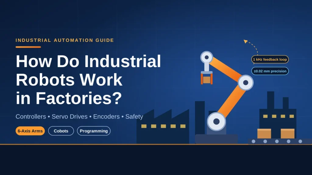
Quick Answer: Understanding how do industrial robots work in factories centers on a closed-loop electromechanical system: a central controller calculates inverse kinematics, regulates high-torque servo drives, and monitors optical encoders at 1 kHz to execute sub-millimeter tool motions, repeatable part handling, and automated processing without human intervention.
Key Takeaways for Operations Leaders
- Electromechanical Core: Industrial robots combine multi-axis joint linkages, brushless AC servo motors, zero-backlash harmonic drives, and absolute optical encoders for deterministic spatial positioning.
- Kinematic Computing: The robot controller translates desired 3D path coordinates ($X, Y, Z, \text{Roll}, \text{Pitch}, \text{Yaw}$) into individual joint angles via real-time inverse kinematics algorithms.
- Programming Diversity: Facilities deploy three primary programming workflows: handheld teach pendants for point-to-point jogging, lead-through kinesthetic teaching for cobots, and 3D digital twin offline programming (OLP) to avoid production downtime.
- Morphology Selection: Factories match specific tasks to five primary robot configurations: 6-axis articulated arms, SCARA, Cartesian gantries, delta spiders, and collaborative cobots.
- Cell Safety Frameworks: Modern robot integration balances mechanical fencing and optical light curtains with ISO 10218-1/2 safety protocols and monitored power-and-force limiting.
Modern manufacturing environments face mounting pressure to accelerate production velocity, eradicate product defects, and safeguard personnel from hazardous working conditions. When engineering teams explore how do industrial robots work in factories, they encounter an intricate union of mechanical design, closed-loop electrical actuation, and deterministic computer software. Rather than acting as isolated gadgets, factory robots function as synchronized execution nodes that turn abstract digital CAD data into rapid, repeatable physical operations.
Understanding how do industrial robots work in factories requires looking past the outward robotic arm structure to inspect the underlying control loops, transmission gears, and sensor feedback networks that make continuous industrial operation possible.
The Core Working Principle: How Industrial Robots Move and Execute Tasks
At the most fundamental mechanical level, investigating how do industrial robots work in factories reveals a continuous electromechanical cycle. The robot receives target positional coordinates from its stored routine, calculates necessary joint movements, delivers measured electrical currents to its drive motors, and monitors physical motion to correct minute positional errors in fractions of a millisecond.
The Closed-Loop Feedback Architecture: Controller, Drive, and Encoder
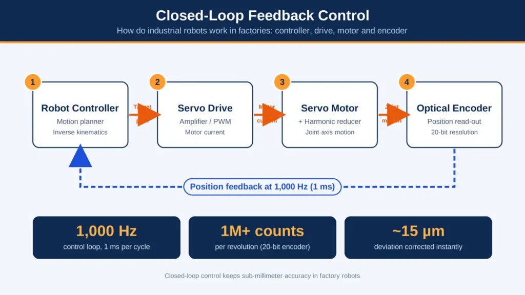
To understand how do industrial robots work in factories during high-speed maneuvers, engineers inspect the closed-loop control architecture operating at high sample frequencies:
- The Trajectory Planner: The central Industrial Robot Controller (IRC) evaluates target path coordinates and generates smooth velocity and acceleration curves.
- Servo Drive Power Modulation: The controller passes digital motion commands to servo amplifier drives, which modulate pulse-width voltage delivered to synchronous AC servo motors.
- Continuous Encoder Feedback: Mounted directly to motor shafts, absolute optical encoders read angular rotation with resolutions exceeding 20 bits (over one million counts per revolution). The drive constantly compares actual joint position against commanded position, eliminating drift.
This closed-loop feedback loop cycles at roughly 1,000 Hz (1 millisecond intervals). When analyzing how do industrial robots work in factories with sub-millimeter tolerances, this millisecond correction loop ensures that if mechanical resistance knocks the tool off path by even 15 microns, the drive detects current error and applies corrective counter-torque immediately.
+------------------+       Target Path       +---------------+
|  Robot Controller| ----------------------> |  Servo Drive  |
|  (Motion Planner)|                         |  (Amplifier)  |
+------------------+                         +---------------+
        ^                                            |
        | Feedback Data                              | Motor Current
        | (1 kHz Loop)                               v
+------------------+       Joint Axis        +---------------+
| Optical Encoder  | <---------------------- |  Servo Motor  |
| (Position Read)  |                         |  & Reducer    |
+------------------+                         +---------------+
Understanding Kinematics: Forward vs. Inverse Kinematics
Calculating multi-axis motion is among the most demanding mathematical tasks when studying how do industrial robots work in factories:
- Forward Kinematics: Computes the final 3D spatial position and orientation of the robot’s tool tip ($X, Y, Z, \text{Roll}, \text{Pitch}, \text{Yaw}$) when each individual joint angle ($\theta_1, \theta_2, \dots, \theta_6$) is known.
- Inverse Kinematics: Operates in reverse. Given a specific coordinate in the factory workspace where a part must be picked, the controller calculates the exact combination of joint angles required to position the tool tip at that point without colliding with the robot’s own chassis.
Because six-axis geometry often yields multiple mathematical solutions for the same Cartesian coordinate (elbow-up versus elbow-down configurations), analyzing how do industrial robots work in factories demonstrates that the motion planner chooses the kinematic path that minimizes joint travel time and energy expenditure.
Precision Motion Transmission: Harmonic Drives and Cycloidal Reducers
Electric servo motors spin at thousands of revolutions per minute, yet observing how do industrial robots work in factories highlights the need for slow, high-torque, backlash-free movements. To achieve this, robotic joints incorporate specialized mechanical speed reducers:
- Harmonic Drives (Strain Wave Gearing): Utilize a flexible elliptical gear mesh that delivers massive gear reduction ratios (up to 160:1) in a compact, zero-backlash form factor. These units dominate wrist and forearm axes.
- Cycloidal Reducers: Employ rolling pins and cycloidal discs to absorb extreme shock loads and deliver high torsional rigidity. These heavy-duty gearboxes anchor robot bases and shoulders.
Engineering Rule of Thumb: Kinematic singularities occur when two robot joint axes align in parallel, causing the mathematical Jacobian matrix to collapse. When examining how do industrial robots work in factories, programmers ensure waypoints approach targets with an offset angle to prevent joint motors from attempting infinite angular velocity.
5 Anatomical Systems of a Factory Industrial Robot
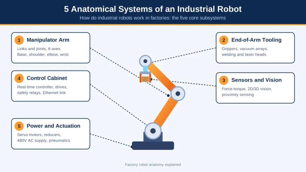
Answering how do industrial robots work in factories requires breaking down the physical machine into five core subsystems.
       [Central Control Cabinet]
                  |
        (Profinet / EtherCAT)
                  v
[Manipulator Arm] ===> [Joint Reducers / Servos]
         |
         +===> [Sensors & Machine Vision]
         |
         +===> [End-of-Arm Tooling (EOAT)]
1. The Manipulator Arm (Links and Mechanical Joints)
At the core of how do industrial robots work in factories is the physical manipulator arm.
When evaluating how do industrial robots work in factories, the physical structure consists of cast aluminum or ductile iron arm segments connected by rotary or linear joints. Each joint provides one degree of freedom (DoF). A traditional six-axis articulated robot features:
- Axis 1 (Base): Sweeps the manipulator arm across the horizontal plane.
- Axis 2 (Shoulder): Extends the lower arm forward and backward.
- Axis 3 (Elbow): Raises and lowers the upper arm vertically.
- Axes 4, 5, and 6 (Wrist): Provide roll, pitch, and yaw articulation to orient the tool tip at any arbitrary angle in 3D space.
2. End-of-Arm Tooling (EOAT): The Working Hands
The robot wrist terminates at an ISO standard mechanical mounting flange. A key aspect of how do industrial robots work in factories involves bolting application-specific End-of-Arm Tooling (EOAT) to this flange to engage physical parts:
- Mechanical Grippers: Pneumatic or electric parallel jaws with custom-machined urethane fingers.
- Vacuum Arrays: Venturi-driven suction cups engineered to lift smooth sheet metal and corrugated packaging.
- Process Tooling: High-frequency arc welding torches, fiber laser cutting heads, sealant dispensers, or electric routing spindles.
3. Sensor Ecosystem: Machine Vision, Force-Torque, and Proximity
Modern industrial robots do not work blind. Six-axis force-torque sensors installed between the robot wrist flange and the gripper measure micro-Newton forces during delicate component insertions. High-speed 2D and 3D machine vision systems locate parts randomly placed in shipping totes, feeding spatial coordinate corrections directly into the motion planner. For software engineers exploring how do industrial robots work in factories, mastering systematic robotics programming allows the robot to adapt trajectory curves instantly based on live vision data.
4. The Central Control Cabinet (The Brain)
Mounted outside the safety fence, the control cabinet houses the industrial computer (running a hard real-time operating system like VxWorks or real-time Linux), servo drives, safety relays, and 24V DC power supplies. Demonstrating how do industrial robots work in factories from a digital standpoint, the cabinet communicates with factory networks over deterministic industrial Ethernet protocols, arbitrating safety stop loops and executing motion trajectory code.
5. Power Supply and Actuation (Servo Motors & Pneumatics)
Three-phase 480V AC utility power enters the control cabinet, where rectifier modules convert it to a high-voltage DC bus. Inverters then distribute pulse-width modulated AC power to individual joint servo motors. Simultaneously, observing how do industrial robots work in factories shows that regulated compressed air lines route through internal arm cavities to actuate pneumatic grippers and air-blow nozzles.
5 Major Types of Industrial Robots Used in Modern Manufacturing
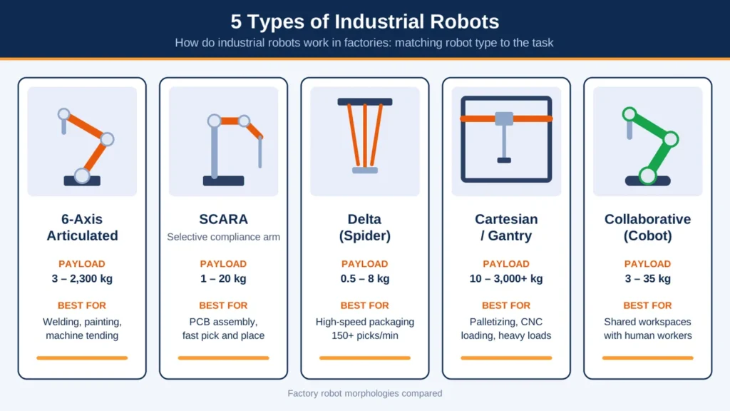
To master how do industrial robots work in factories, plant managers must differentiate the mechanical morphologies suited for specific shop-floor workloads.
1. 6-Axis Articulated Robots
The workhorse of heavy manufacturing. Articulated robots feature six revolute joints that deliver a near-spherical work envelope. They mimic the motion range of a human arm with far greater payload capacity (from 3 kg up to 2,300 kg) and sub-millimeter precision. When observing how do industrial robots work in factories, common articulated duties include automotive body welding, structural painting, foundry casting extraction, and machine tending.
2. SCARA Robots (Selective Compliance Articulated Robot Arm)
SCARA robots feature two parallel rotary joints that provide compliant movement in the horizontal X-Y plane, paired with a rigid vertical Z-axis spline. This configuration yields exceptional rigidity along the vertical axis while enabling blindingly fast horizontal pick-and-place motions. In electronics manufacturing, studying how do industrial robots work in factories reveals SCARA robots as standard fixtures across semiconductor packaging, printed circuit board (PCB) assembly, and pharmaceutical sorting lines.
3. Delta (Spider) Robots
Constructed from three or four lightweight parallelogram linkage arms connected to a shared base plate suspended overhead. Delta robots maintain all heavy drive motors stationary in the ceiling base, allowing the lightweight End-of-Arm Tooling to accelerate at rates exceeding $15G$. When plant managers examine how do industrial robots work in factories handling consumer packaged goods, Delta robots lead high-speed primary packaging, sorting items off moving conveyors at over 150 picks per minute.
4. Cartesian / Gantry Robots
Cartesian robots operate along three orthogonal linear axes ($X, Y, Z$) using linear ball-screw or belt-driven actuators. Their rectilinear envelope allows them to span enormous floor plans with immense load-bearing rigidity. Reviewing how do industrial robots work in factories with heavy payloads shows overhead Cartesian gantries moving full automotive engine blocks, loading CNC lathes, and organizing high-volume warehouse palletizing.
5. Collaborative Robots (Cobots)
Unlike traditional industrial robots that operate inside isolated enclosures, cobots feature rounded chassis profiles, integrated joint torque sensors, and force-limiting control logic that stops motion instantly upon detecting unexpected contact with a human. Understanding how do industrial robots work in factories with shared human workspaces showcases cobots automating low-payload packaging, quality inspection, and machine feeding while working side-by-side with plant personnel.
Kinematics Comparison Matrix
| Robot Architecture | Kinematic Axes (DoF) | Typical Payload Range | Positional Repeatability | Footprint & Work Envelope | Ideal Factory Workload |
| 6-Axis Articulated | 6 (Rotational) | 5 kg – 1,500+ kg | $\pm 0.02\text{ mm}$ to $\pm 0.1\text{ mm}$ | Compact base, large spherical reach | Arc/spot welding, palletizing, heavy tending |
| SCARA | 4 (2 Rotational, 2 Linear) | 1 kg – 20 kg | $\pm 0.01\text{ mm}$ to $\pm 0.025\text{ mm}$ | Small cylindrical envelope | PCB assembly, screw driving, fast insertion |
| Delta (Spider) | 3 to 4 (Parallel) | 0.5 kg – 8 kg | $\pm 0.05\text{ mm}$ to $\pm 0.1\text{ mm}$ | Overhead ceiling mount, dome envelope | High-speed packaging, bin sorting (150+ picks/min) |
| Cartesian / Gantry | 3 to 5 (Linear) | 10 kg – 3,000+ kg | $\pm 0.05\text{ mm}$ to $\pm 0.2\text{ mm}$ | Overhead rectangular gantry structure | Heavy machine tending, large panel cutting |
| Collaborative (Cobot) | 6 to 7 (Rotational) | 3 kg – 35 kg | $\pm 0.03\text{ mm}$ to $\pm 0.05\text{ mm}$ | Highly compact, circular workspace | Shared assembly, end-of-line testing, sanding |
How Industrial Robots Are Programmed on the Factory Floor
A critical dimension of how do industrial robots work in factories involves how technicians teach machines their production paths. Modern factories deploy three distinct programming paradigms based on task complexity.
Method 1: Teach Pendant Programming (Point-to-Point and Linear Interpolation)
When training shop-floor technicians on how do industrial robots work in factories, the teach pendant remains the primary physical programming interface.
The teach pendant remains the standard interface when establishing how do industrial robots work in factories during initial cell setup. A technician holds an ergonomic handheld tablet connected to the control cabinet via an umbilical cable:
- Jogging Modes: The operator switches between Joint Jogging (moving individual motor axes) and World/Tool Cartesian Jogging (moving the tool tip along straight $X, Y, Z$ planes).
- Waypoint Recording: The technician maneuvers the tool tip to an operational position and presses a record key, storing point data ($P_1, P_2, \dots$).
- Motion Commands: In the robot’s language (such as KUKA KRL, FANUC TP, ABB RAPID, or Yaskawa INFORM), the programmer specifies motion types:
MOVEJ(Joint Motion): Moves all axes simultaneously at maximum speed without maintaining a straight line; used for transit clearance.MOVEL(Linear Motion): Forces the Tool Center Point to travel along a mathematically straight line; mandatory for welding, dispensing, and insertion.
Method 2: Lead-Through & Hand-Guiding (Kinesthetic Teaching)
Another intuitive approach to understanding how do industrial robots work in factories involves direct kinesthetic teaching.
Primarily utilized with collaborative robots, lead-through programming removes textual code entry when configuring how do industrial robots work in factories. The operator presses a free-drive button on the robot wrist, physically grasping the End-of-Arm Tooling and guiding it through the desired trajectory. The internal joint encoders record positional waypoints at steady intervals. This approach enables shop-floor operators without coding experience to program complex fluid dispensing beads or machine loading routines in minutes.
Method 3: Offline Programming (OLP) and Digital Twin Simulation
Shutting down an active automotive or aerospace production line to teach robot points manually can cost thousands of dollars per minute in lost output. Evaluating how do industrial robots work in factories under lean operational parameters highlights the role of Offline Programming (OLP). Software engineers import 3D CAD models of the factory cell, tooling, and workpieces into simulation software (such as Siemens Process Simulate, ABB RobotStudio, or RoboDK).
Engineers program complete motion paths, verify joint limits, check for physical tool collisions, and optimize cycle times virtually. The software then compiles the simulation into vendor-native robot code and uploads it directly to the factory floor controller. Incorporating emerging tech trends like virtual commissioning and physics-based digital twins drastically shortens physical plant commissioning from weeks to days.
Calibrating Tool Center Point (TCP) and Coordinate Frames
When investigating how do industrial robots work in factories with extreme accuracy, technicians must calibrate several coordinate frames:
- World Frame: The absolute Cartesian coordinate reference frame of the factory floor ($X=0, Y=0, Z=0$).
- Base Frame: Centered at the physical base casting of the robot.
- Tool Center Point (TCP): The exact working coordinate at the functional tip of the tooling (e.g., the tip of a welding wire or center of gripper pads). Technicians calibrate the TCP by approaching a fixed reference pointer from four distinct orientations, allowing the controller to calculate exact tool offset vectors ($X, Y, Z, \text{Yaw}, \text{Pitch}, \text{Roll}$).
Factory Integration: How Robots Communicate with Factory Systems
Industrial robots do not operate in a vacuum; they form an interconnected node within the broader factory production matrix. Understanding how do industrial robots work in factories requires reviewing how robots communicate with upstream and downstream equipment.
Interfacing with Programmable Logic Controllers (PLCs) and Line Conveyors
In a typical production cell, an overarching Programmable Logic Controller (PLC) acts as the cell conductor. Reviewing how do industrial robots work in factories shows that the robot and PLC communicate via discrete digital handshakes:
- Infeed Clear Signal: The conveyor PLC signals the robot that a raw workpiece is clamped in position and ready for picking.
- Robot Busy Bit: The robot raises a digital output bit confirming it is inside the clearance zone, instructing the conveyor not to index.
- Cycle Complete Bit: The robot finishes its operation, clears the interference envelope, and signals the downstream station to advance.
When coordinating multiple automated cells across an enterprise, aligning physical robotic material handling with broader process automation ensures information flow between enterprise ERP systems and physical shop-floor assets remains synchronized.
Real-Time Fieldbus Protocols: Profinet, EtherCAT, and Ethernet/IP
Legacy hardwired I/O relays have been replaced by deterministic industrial Ethernet fieldbuses. When looking at how do industrial robots work in factories with synchronized line tracking, protocols like Profinet IRT or EtherCAT allow a single industrial Ethernet cable to carry thousands of digital inputs, pneumatic valve signals, and drive diagnostic packets with sub-millisecond jitter.
Connecting to MES and Industrial IoT for Predictive Maintenance
Modern robots constantly stream performance telemetry to factory Manufacturing Execution Systems (MES). High-speed IoT edge gateways monitor motor winding temperature profiles, harmonic vibration signatures in joint reducers, and cumulative drive current draw. Connecting these robotic assets with experienced partners in IoT development allows plant managers to run predictive maintenance algorithms, replacing worn gear sets before an unpredicted mechanical failure halts plant production. Furthermore, as vision-guided inspection models become increasingly autonomous, instituting an AI governance framework ensures that neural network models handling defect classification remain traceable and compliant.
Safety Architecture: Protecting Human Workers in Robotic Cells
High-payload industrial robots accelerate rapidly with immense mechanical torque, presenting severe hazards to human operators. A foundational component of how do industrial robots work in factories is the multi-layered safety architecture designed to prevent accidental physical impact.
+---------------------------------------------------------------+
|                      Work Cell Perimeter                      |
|                                                               |
|   +-------------------------------------------------------+   |
|   |                 Optical Light Curtain                 |   |
|   |                                                       |   |
|   |     +-------------------------------------------+     |   |
|   |     |           Robot Hazard Envelope           |     |   |
|   |     |                                           |     |   |
|   |     |                [Robotic Arm]              |     |   |
|   |     |                                           |     |   |
|   |     +-------------------------------------------+     |   |
|   |                                                       |   |
|   +-------------------------------------------------------+   |
|                                                               |
+---------------------------------------------------------------+
Traditional Safeguarding: Interlocked Fencing and Optical Light Curtains
Heavy articulated robots operate inside physical perimeter fencing. Interlocked safety gate switches cut power to motor drives via dual-channel safety contactors whenever an operator opens an access gate. Across loading stations where parts pass into the cell, infrared optical light curtains project dense arrays of invisible beams; breaking a single beam triggers a Category 4 emergency stop within milliseconds.
Industrial Regulatory Standards: ISO 10218-1/2 and ISO/TS 15066
Any engineer auditing how do industrial robots work in factories must verify that installations comply with strict ISO guidelines governing the safe design, integration, and risk assessment of industrial robot systems. Standard ISO 10218-1 details technical requirements for robot manufacturers, while ISO 10218-2 guides system integrators deploying full work cells.
The 4 Cobot Collaborative Operating Modes
For collaborative workstations operating without perimeter fencing, standard ISO/TS 15066 defines four permitted operational modes:
- Safety-Rated Monitored Stop: The cobot operates autonomously at high speed while workers remain outside its proximity zone. When a worker steps into the shared space, the robot pauses motion and locks joint brakes without dropping power.
- Hand Guiding: The operator moves the robot arm manually using a certified enabling grip device on the wrist.
- Speed and Separation Monitoring: Laser area scanners monitor safety zones around the robot. As a human approaches, the robot progressively throttles speed; if the worker breaches the inner boundary, the robot halts completely.
- Power and Force Limiting: Joint torque sensors and motor current limiters guarantee that if the robot makes accidental contact with a human, impact force remains below bio-mechanical injury thresholds.
Frequently Asked Questions About Industrial Robots
How do industrial robots work?
Industrial robots operate through a closed-loop electromechanical cycle. A central controller computes inverse kinematics, sending power to brushless AC servo motors. While joint linkages articulate through zero-backlash reducers, optical encoders stream positional feedback at 1,000 Hz, instantly correcting micro-deviations to maintain sub-millimeter trajectory accuracy.
What are 10 disadvantages of industrial robots?
Key disadvantages include high upfront CAPEX, specialized programming needs, infeed tolerance sensitivity, safety cage footprint requirements, and expensive retooling. Additionally, robots face ongoing preventive maintenance costs, lack human manual dexterity, depend on heavy utility infrastructure, present network cybersecurity risks, and require workforce retraining.
Who is the largest manufacturer of industrial robots in the world?
Japan’s FANUC Corporation is the world’s largest industrial robot manufacturer by installed base, with over one million robots deployed globally. Alongside FANUC, the international industrial automation market is anchored by three other robotics giants: Yaskawa Electric, ABB, and KUKA.
Can you give me five examples of industrial robots?
Five primary industrial models include the FANUC M-2000iA (heavy automotive assembly), KUKA KR CYBERTECH (precision welding), Epson LS3-B (high-speed electronics SCARA), ABB IRB 360 FlexPicker (delta packaging robot), and Universal Robots UR10e (collaborative machine tending cobot).
How long do industrial robots typically last in factories?
Industrial robots deliver an operational service life of 10 to 15 years, frequently exceeding 60,000 to 100,000 continuous production hours. With scheduled lubrication and motor maintenance, cast mechanical arms last decades, while modular components like wrist cables and servo drives are rebuilt periodically.
Can industrial robots replace human workers entirely?
No. Industrial robots eliminate dull, repetitive, and ergonomically hazardous tasks like spot welding and heavy palletizing. However, manufacturing plants still depend on human operators, controls engineers, and technicians for trajectory programming, tooling changeovers, unexpected exception handling, and continuous process optimization.
The Future of Factory Robotics
Industrial robotics is transitioning from rigid, blind execution toward adaptive, cognitive automation. The convergence of high-resolution 3D vision, edge AI processing, and real-time kinematic adaptability allows modern factory robots to handle variable incoming components without custom mechanical fixtures. As manufacturing facilities continue seeking higher throughput, reduced carbon footprint, and operational resilience, understanding how do industrial robots work in factories serves as the technical foundation for modernizing any production facility.